Removal of Shipping Braces
Prior to being shipped from Cardiff, a number of shipping braces were installed within MUSCAT to help protect the weak mechanical supports from damage during shipping. Prior to use, these will need to be carefully removed and some components reinstalled within MUSCAT.
Fixings and other parts that need installing after the braces have been removed are contained in a cardboard box (Shipping List number #1-2), which is strapped to the side of MUSCAT.
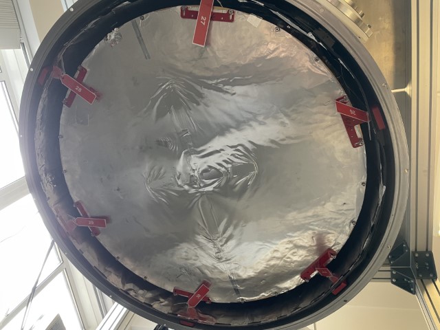
50 K Stage braces
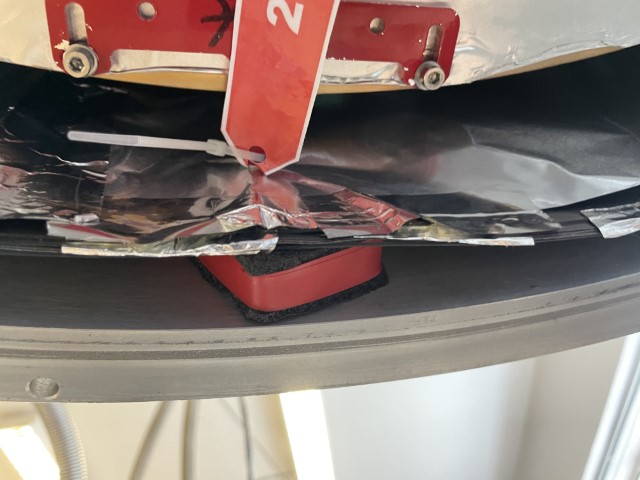
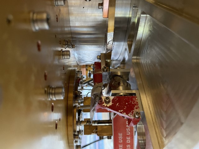
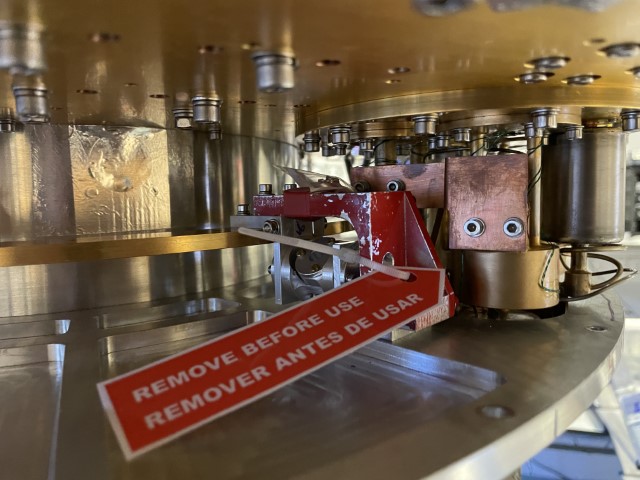
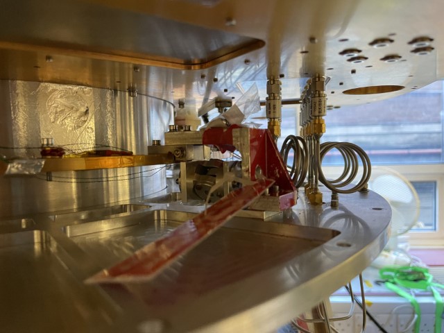
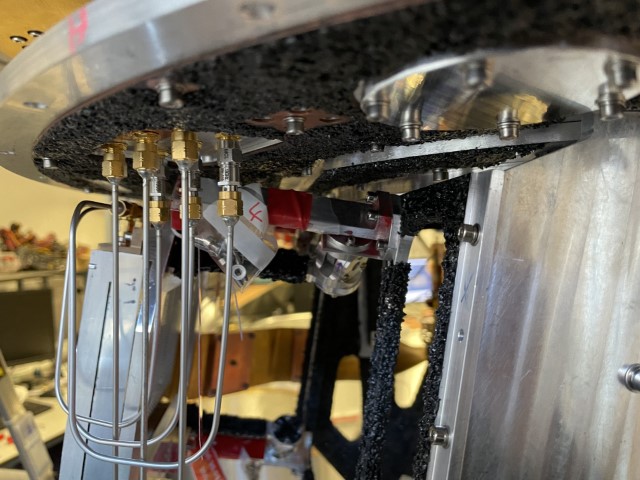
The braces support the bottom end of the 50 K shield adding radial struts which brace the shield to the inside of the vacuum shield. The braces brace against the inner lining of the vacuum shield and a foam padding block is placed between the lining and the inner wall of the vacuum can.
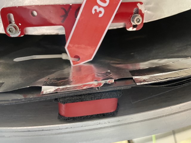
Brace 30
Prior To Removal: Note the position of the alignment marks on the bottom plate of the vacuum shield to help when reinstalling the plate. With MUSCAT on the working frame, slowly vent the vacuum via the side port, the ingression of air to the cryostat should be as slow as possible and only just audible. With the bottom plate of the cryostat fully supported, remove and store the bolts securing this plate to the cryostat. Slowly lower the plate away from the main body of the cryostat ensuring the O-ring remains within the groove in the plate.
Take care to protect O-ring and vacuum surfaces while removing bottom plate.
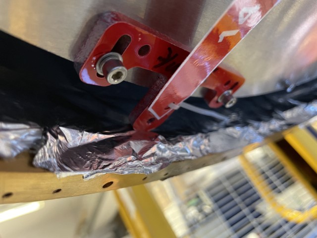
To Remove: Loosen 2 x M4 bolts and slide brace towards the centre of the cryostat, away from the inner wall of the 4 K can. Remove black foam shipping padding, marked with red tape, located between OVC inner wall and lining. Remove 2 x M4 bolts fully and remove brace. Take care not to damage lining when removing brace.
After Removal: From Bag 30 (in box): 2 x M4 bolts with spring washer and flat washer into two bolt holes vacated by removal of brace.
Brace 29
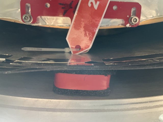
To Remove: Loosen 2 x M4 bolts and slide brace towards the centre of the cryostat, away from the inner wall of the 4 K can. Remove black foam shipping padding, marked with red tape, located between OVC inner wall and lining. Remove 2 x M4 bolts fully and remove brace. Take care not to damage lining when removing brace.
After Removal: From Bag 29 (in box): 2 x M4 bolts with spring washer and flat washer into two bolt holes vacated by removal of brace.
Brace 28
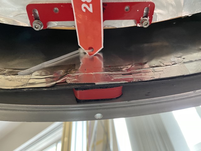
To Remove: Loosen 2 x M4 bolts and slide brace towards the centre of the cryostat, away from the inner wall of the 4 K can. Remove black foam shipping padding, marked with red tape, located between OVC inner wall and lining. Remove 2 x M4 bolts fully and remove brace. Take care not to damage lining when removing brace.
After Removal: From Bag 28 (in box): 2 x M4 bolts with spring washer and flat washer into two bolt holes vacated by removal of brace.
Brace 27
To Remove: Loosen 2 x M4 bolts and slide brace towards the centre of the cryostat, away from the inner wall of the 4 K can. Remove black foam shipping padding, marked with red tape, located between OVC inner wall and lining. Remove 2 x M4 bolts fully and remove brace. Take care not to damage lining when removing brace.
After Removal: From Bag 27 (in box): 2 x M4 bolts with spring washer and flat washer into two bolt holes vacated by removal of brace.
Brace 26
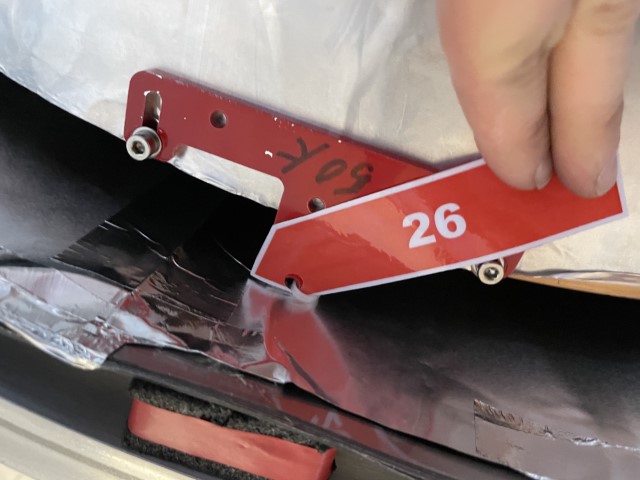
To Remove: Loosen 2 x M4 bolts and slide brace towards the centre of the cryostat, away from the inner wall of the 4 K can. Remove black foam shipping padding, marked with red tape, located between OVC inner wall and lining. Remove 2 x M4 bolts fully and remove brace. Take care not to damage lining when removing brace.
After Removal: From Bag 26 (in box): 2 x M4 bolts with spring washer and flat washer into two bolt holes vacated by removal of brace.
Brace 25
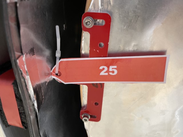
To Remove: Loosen 2 x M4 bolts and slide brace towards the centre of the cryostat, away from the inner wall of the 4 K can. Remove black foam shipping padding, marked with red tape, located between OVC inner wall and lining. Remove 2 x M4 bolts fully and remove brace. Take care not to damage lining when removing brace.
After Removal: From Bag 25 (in box): 2 x M4 bolts with spring washer and flat washer into two bolt holes vacated by removal of brace. Carefully raise vacuum shield's bottom plate into position, orientating by alignment marks, and reinstall all perimeter bolts. Tighten opposite bolts sequentially to ensure even compression of O-ring and level installation of plate.
When reinstalling bottom OVC plate, make sure O-ring, O-ring grove and mating surface are all clean. Make sure O-ring is located in grove correctly prior to reinstalling plate and that the O-ring does not move during mounting of the plate.
The outer vacuum can should now be removed as normal.
4 K Stage Braces
Brace 24
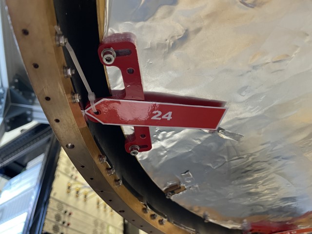
Prior To Removal: Support 50 K can's bottom plate from underneath and remove perimeter bolts and store. Also remove and store diode. With all bolts removed lower lid of 50 K can.
To Remove: Loosen 2 x M4 bolts and slide brace towards the centre of the cryostat, away from the inner wall of the 4 K can. Remove 2 x M4 bolts fully and remove brace. Take care not to damage lining when removing brace.
After Removal: From Bag 24 (in box): 2 x M4 bolts with spring washer and flat washer into two bolt holes vacated by removal of brace
Brace 23
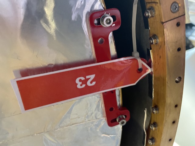
To Remove: Loosen 2 x M4 bolts and slide brace towards the centre of the cryostat, away from the inner wall of the 4 K can. Remove 2 x M4 bolts fully and remove brace. Take care not to damage lining when removing brace.
After Removal: From Bag 23 (in box): 2 x M4 bolts with spring washer and flat washer into two bolt holes vacated by removal of brace
Brace 22
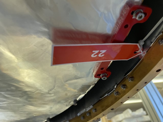
To Remove: Loosen 2 x M4 bolts and slide brace towards the centre of the cryostat, away from the inner wall of the 4 K can. Remove 2 x M4 bolts fully and remove brace. Take care not to damage lining when removing brace.
After Removal: From Bag 22 (in box): 2 x M4 bolts with spring washer and flat washer into two bolt holes vacated by removal of brace.
Brace 21
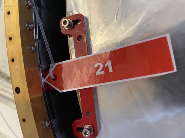
To Remove: Loosen 2 x M4 bolts and slide brace towards the centre of the cryostat, away from the inner wall of the 4 K can. Remove 2 x M4 bolts fully and remove brace. Take care not to damage lining when removing brace.
After Removal: From Bag 21 (in box): 2 x M4 bolts with spring washer and flat washer into two bolt holes vacated by removal of brace.
Brace 20
To Remove: Loosen 2 x M4 bolts and slide brace towards the centre of the cryostat, away from the inner wall of the 4 K can. Remove 2 x M4 bolts fully and remove brace. Take care not to damage lining when removing brace.
After Removal: From Bag 20 (in box): 2 x M4 bolts with spring washer and flat washer into two bolt holes vacated by removal of brace.
Brace 19
To Remove: Loosen 2 x M4 bolts and slide brace towards the centre of the cryostat, away from the inner wall of the 4 K can. Remove 2 x M4 bolts fully and remove brace. Take care not to damage lining when removing brace.
After Removal: From Bag 19 (in box): 2 x M4 bolts with spring washer and flat washer into two bolt holes vacated by removal of brace. After bolts are reinstalled, replace 50 K shield lid orientating by marked diode position. Reconnect cable to diode with black mark pointing outwards, secure with aluminium tape as needed. Replace bolts in 50 K shield's bottom plate. Support 50 K can from underneath and remove as normal. Support 50 K shield from underneath and remove as normal.
450 mK Stage Braces
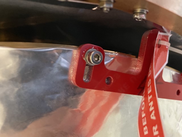
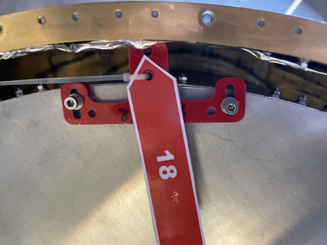
Brace 18
Prior To Removal: Not the position of the diode thermometer and the markings on the shield. With the 4 K shield's bottom plate supported from underneath, remove the plate's bolts and store. Also remove and store diode. Lower plate away from shield.
To Remove: Loosen 2 x M4 bolts and slide brace towards the centre of the cryostat, away from the inner wall of the 4 K can. Remove 2 x M4 bolts fully and remove brace. Take care not to damage lining when removing brace.
After Removal: From Bag 18 (in box): 2 x M4 bolts with spring washer and flat washer into two bolt holes vacated by removal of brace.
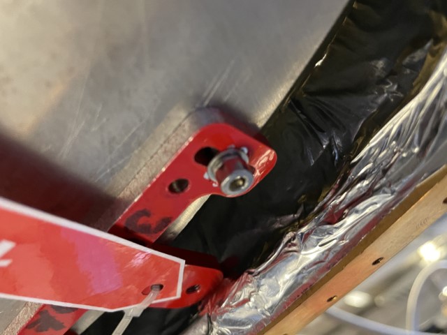
Brace 17
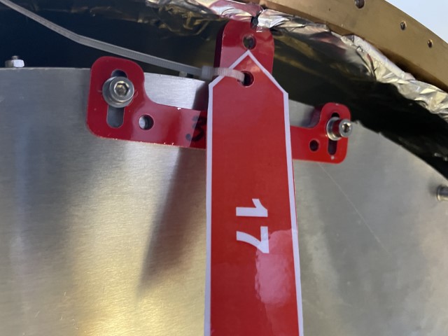
To Remove: Loosen 2 x M4 bolts and slide brace towards the centre of the cryostat, away from the inner wall of the 4 K can. Remove 2 x M4 bolts fully and remove brace. Take care not to damage lining when removing brace.
After Removal: From Bag 17 (in box): 2 x M4 bolts with spring washer and flat washer into two bolt holes vacated by removal of brace.
Brace 16
To Remove: Loosen 2 x M4 bolts and slide brace towards the centre of the cryostat, away from the inner wall of the 4 K can. Remove 2 x M4 bolts fully and remove brace. Take care not to damage lining when removing brace.
After Removal: From Bag 16 (in box): 2 x M4 bolts with spring washer and flat washer into two bolt holes vacated by removal of brace.
Brace 15
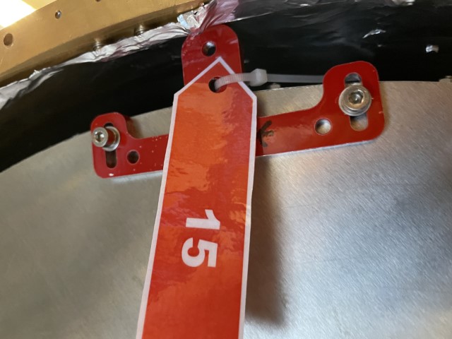
To Remove: Loosen 2 x M4 bolts and slide brace towards the centre of the cryostat, away from the inner wall of the 4 K can. Remove 2 x M4 bolts fully and remove brace. Take care not to damage lining when removing brace.
After Removal: From Bag 15 (in box): 2 x M4 bolts with spring washer and flat washer into two bolt holes vacated by removal of brace.
Brace 14
To Remove: Loosen 2 x M4 bolts and slide brace towards the centre of the cryostat, away from the inner wall of the 4 K can. Remove 2 x M4 bolts fully and remove brace. Take care not to damage lining when removing brace.
After Removal: From Bag 14 (in box): 2 x M4 bolts with spring washer and flat washer into two bolt holes vacated by removal of brace.
Brace 13
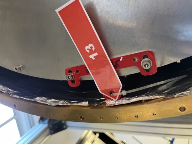
To Remove: Loosen 2 x M4 bolts and slide brace towards the centre of the cryostat, away from the inner wall of the 4 K can. Remove 2 x M4 bolts fully and remove brace. Take care not to damage lining when removing brace.
After Removal: From Bag 14 (in box): 2 x M4 bolts with spring washer and flat washer into two bolt holes vacated by removal of brace. After bolts are reinstalled, replace 4 K shield's bottom plate, orientating by marked diode position. Reroute cable to diode across the bottom of the 4 K shield lid, secure with aluminium tape. Support 4 K shield from underneath and remove as normal.
When reinstalling the 4 K can lid, make sure the outer lining is supported as this is only secured by the washers.
Extreme care is needed when removing the 450 mK shield to avoid catching/damaging the array, coax cables or mirrors. This takes two people; the shield cannot be levelled evenly but instead needs to be lowered one side at a time in stages.
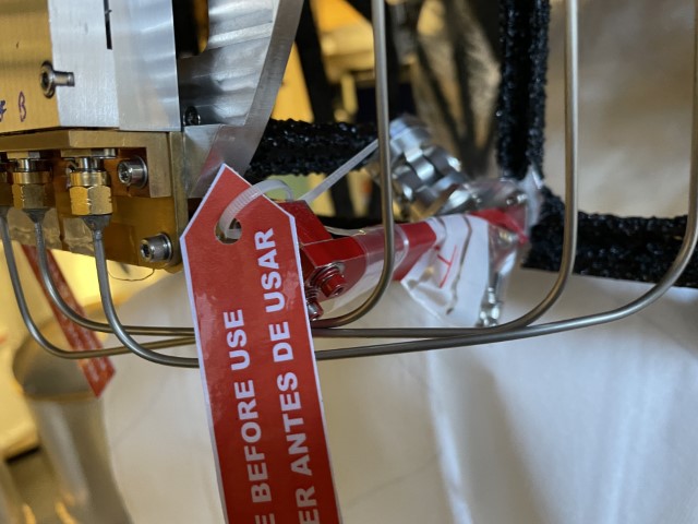
1 K Ring Braces
Brace 12
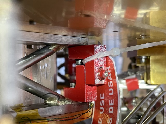
Location: Near Coax Cabling
To Remove: Remove red bolt connecting two parts of brace, removing bolt, spring washer and flat washer. Remove lower brace segment, removing bolt, spring washer, flat washer and nut. Remove upper brace removing bolt and flat washer.
This should be possible without removal of coax. If coax needs to be removed, extreme care should be taken not to break the solder joints.
After Removal: From Bag 12 (in box): 1 x longer M3 bolt through ring and lower cross-beam foot (from underside), on plate side: spring washer, on cross-beam side, flat washer, spring washer and nut. 1 x shorter M3 bolt, through upper cross-beam foot and into 4 K plate. With spring and flat washer.
Brace 11
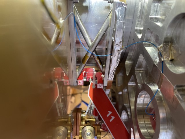
Location: Near Mechanical Heat Switch
To Remove: Remove bolt connecting two parts of the brace, this should be possible by undoing socket cap but short 5.5 mm spanner may be required to remove backside bolt first. Remove lower brace segment, removing bolt, spring washer, flat washer and nut. Remove upper brace removing bolt and flat washer.
Take care of nearby micro-D connector (could be removed in preparation of brace 8), mechanical heat switch mechanism and the exposed optical fibre.
After Removal: From Bag 11 (in box): 1 x longer M3 bolt through ring and lower cross-beam foot (from underside), on plate side: spring washer, on cross-beam side, flat washer, spring washer and nut. 1 x shorter M3 bolt, through upper cross-beam foot and into 4 K plate. With spring and flat washer. Re attached cryo loom to cross brace and secure with Kapton tape if needed.
Brace 10
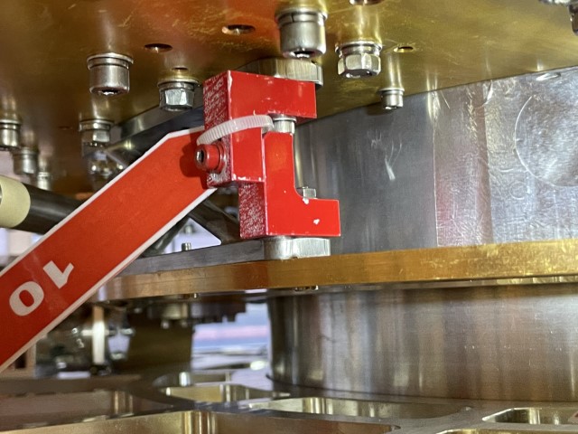
Location: Near Gas-Gap Heatswitch
To Remove: Remove red bolt connecting two parts of brace, removing bolt, spring washer and flat washer. Remove lower brace segment, removing bolt, spring washer, flat washer and nut. Remove upper brace removing bolt and flat washer.
Take care of gas-gap heat switch, nearby sapphire joint (Brace Number 6) and 4 K PTC braid bolts on underside of 4 K plate.
After Removal: From Bag 10 (in box): 1 x longer M3 bolt through ring and lower cross-beam foot (from underside), on plate side: spring washer, on cross-beam side, flat washer, spring washer and nut. 1 x shorter M3 bolt, through upper cross-beam foot and into 4 K plate. With spring and flat washer.
Brace 9
Location: Near CC7 Fridge
To Remove: Remove red bolt connecting two parts of brace, removing bolt, spring washer and flat washer. Remove lower brace segment, removing bolt, spring washer, flat washer and nut. Remove upper brace removing bolt and flat washer.
Take care of dilutor expansion tank, wiring loom and nearby thermometer.
After Removal: From Bag 9 (in box): 1x longer M3 bolt through ring and lower cross-beam foot (from underside), on plate side: spring washer, on cross-beam side, flat washer, spring washer and nut. 1x shorter M3 bolt, through upper cross-beam foot and into 4 K plate. With spring and flat washer.
450 mK Plate
Brace 8
Location: Near Mechanical Heat Switch
To Remove: 2 x M3 outboard: remove M3 nuts and M3 and M4 washers from underside. From topside remove M3x25 bolt and flat washer. 2 x M3x20 inboard: remove bolts, flat and spring washers.
Removal is made easier by disconnecting the micro-D 9 pin on the 1 K ring.
If needed the 450 mK part (mounted to Al plate) of the heat switch can be removed, the 4 K part and drive must NOT be removed. To remove 450 mK part: Release heat switch at top of cryostat by turning 10 times anti-clockwise. Remove 4 x M3 and spring washers and remove heat switch fingers. To reinstall, remount heat switch finger but leave bolts very loose. Close heat switch by turning clockwise until secure then fully tighten 4 x M3.
After Removal: From Bag 8 (on brace): 2 x long bolts with spring and flat washer through in board (top) sapphire joint bracket from top through bracket into tapped hole in 1 K ring 2 x short bolts with spring washer into outboard bracket (bottom) from underside of 450 mK plate, through plate into bracket After install, re connect micro-D 9 pin and secure wiring. If removed, replace finger of heat switch as described above.
Brace 7
Location: Near CC4 Fridge
To Remove: 2 x M3 outboard: remove M3 nuts and M3 and M4 washers from underside. From topside remove M3x25 bolt and flat washer. 2 x M3x20 inboard: remove bolts, flat and spring washers.
Take care of CC4 fridge and wiring on top side and wire the runs from fridge to ring under brace. Take care of exposed optical fibre on under side.
After Removal: From Bag 7 (on brace): 2 x long bolts with spring and flat washer through in board (top) sapphire joint bracket from top through bracket into tapped hole in 1 K ring. 2 x short bolts with spring washer into outboard bracket (bottom) from underside of 450 mK plate, through plate into bracket. After install, reroute and secure wire from fridge to ring on top of sapphire joint bracket.
Brace 6
Location: Near CC7 Fridge
To Remove: 2 x M3 outboard: remove M3 nuts and M3 and M4 washers from underside. From topside remove M3x25 bolt and flat washer. 2 x M3x20 inboard: remove bolts, flat and spring washers.
Take care of CC7 fridge and wiring
After Removal: From Bag 6 (on brace): 2 x bolts with spring and flat washer through in board (top) sapphire joint bracket from top through bracket into tapped hole in 1 K ring. 2 x bolts with spring washer into outboard bracket (bottom) from underside of 450 mK plate, through plate into bracket.
Brace 5
Location: Near Coax Cabling
To Remove: 2 x M3 outboard: remove M3 nuts and M3 and M4 washers from underside. From topside remove M3x25 bolt and flat washer. 2 x M3x20 inboard: remove bolts, flat and spring washers.
Care to be taken of coax and wiring on 1 K ring.
Focal Plane
Brace 4
To Remove: 2 x M3 bolts at sapphire joints, each with flat and spring washer. 2x M3 stud, one at MD-F-A with nut only on array side and spring washer, flat washer and nut on mirror side. One at MD-F-Centre with flat washer, spring washer and nut on both sides.
After Removal: From Bag 4 (on brace): Short bolts into sapphire joint bracket. Long bolts into array (from SMA side into structure to match rest). Bolt at MD-F-B flat washer only, bolt at MD-F-centre flat and spring washers.
Brace 3
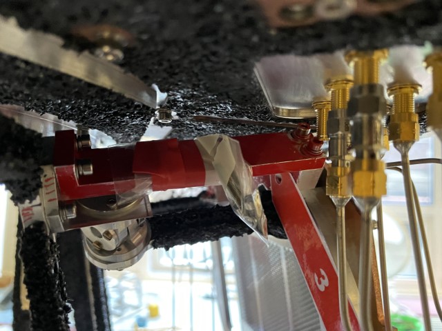
To Remove: 2 x M3 bolts at sapphire joints, each with flat and spring washer. 2x M3 stud, one at MD-M-B with nut only on array side and spring washer, flat washer and nut on mirror side. One at MD-M-Centre with flat washer, spring washer and nut on both sides.
After Removal: Loosen both ends of coax MD-M-B-In and remove from array (spinning on plate connection). From Bag 3 (on brace): Short bolts into sapphire joint bracket. Long bolts into array (from SMA side into structure to match rest). Bolt at MD-M-A flat washer only, bolt at MD-M-centre flat and spring washers. Install ND-J-A-In cable (from box) and tighten all coax SMA connections.
Brace 2
To Remove: 2 x M3 bolts at sapphire joints, each with flat and spring washer. 2x M3 stud, one at MD-M-B with nut only on array side and spring washer, flat washer and nut on mirror side. One at MD-M-Ref with flat washer, spring washer and nut on both sides.
After Removal: From Bag 2 (on brace): Short bolts into sapphire joint bracket Long bolts into array (from SMA side into structure to match rest). Bolt at MD-M-A flat washer only, bolt at MD-M-Ref flat and spring washers.
Take care to avoid focal plane heater wiring
Brace 1
To Remove: 2 x M3 bolts at sapphire joints, each with flat and spring washer. 2 x M3 stud, one at MD-F-A with flat washer and nut on array side and spring washer, flat washer and nut on mirror side. One at MD-F-Ref with flat washer, spring washer and nut on both sides.
May require disconnection of coax MD-J-B-Out and coax MD-F-A-Out at array. Loosen at 450 mK plate underside first.
After Removal: From Bag 1 (on brace): Short bolts into sapphire joint bracket Long bolts into array (from SMA side into structure to match rest). Bolt at MD-F-B flat washer only, bolt at MD-F-Ref flat and spring washers.