The Working Frame
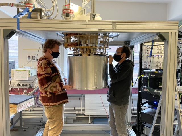
In order to open and close the MUSCAT cryostat it needs to be raised from the floor sufficiently that the vacuum can and radiation shields can be lowered and removed from beneath the cryostat. The working frame was fully dismantled for shipping and all parts are located in shipping crate number 4.
Description
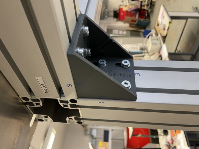
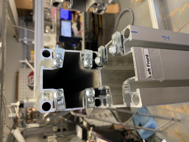
The frame consists of standard T-slot extruded aluminium beams and appropriate fittings. Each beam is labelled with a description, when assembled these labels should have the text facing upwards. On vertical pieces the label should be at the top of the beam, on horizontal pieces the label should be at the left. In all instances the label should face outwards. The front of the frame is defined as the open side which does not have a horizontal beam at the bottom. Each interface is supported by a right-angle bracket and each bracket has been numbered. The fittings (bolts, washers and square nuts) for each bracket are located in bags the cardboard box in crate 4. Each back is numbered to match it's corresponding bracket.
Some interfaces have sliding fitting in addition to the right-angle brackets. These are located at the end of one beam and are slid loose into the other beam and then tightened with a hex key after being aligned.
Top plates
Two large aluminium top plates sit on top of the frame to hold the cryostat. These are designed to be slid slightly open to allow the the cryostat to be raised and lowered between them and then closed to support the cryostat. These are labelled with the same definitions as the beams and brackets and when installed should have alignment marks to the top front and top back beams. Some spring-retained nuts may be pre-installed in the top beams, other fittings are located in the cardboard box.
Drawings
A PDF of the frame design can be downloaded here.