Cryogenics: User Interface
The cooling platform is controlled by the MUSCAT Cryogenics Control and Logging (MC-CAL) software. This allows user control and also manages the state machine used to recycle the sorption coolers and operate the miniature dilution refrigerator.
Interface
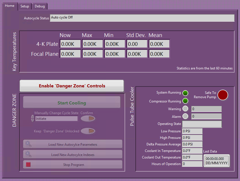
The interface provides the key information about the current state of the cooling system. The focal plane (detector) temperature is shown along with the 4-kelvin plate. The live temperature is shown (left column) along with some basic statistics (minimum and maximum values, and standard divination, and mean) from the last 60 minutes. The current status of the auto cycle is shown at the top of the home tab.
Temperature sensors are measured and logged every two seconds while measurements from the pulse tube cooler compressor are read and logged ever 60 seconds (adjustable).
The MC-CAL program can also be used to start and stop the cooling system of MUSCAT. To protect the system from accidental shut downs etc. the critical controls are disabled and grouped into a "DANGER ZONE". To enable these controls, click the "Enable 'Danger Zone' Controls". This will enable the controls for 10 seconds before, this should be ample time to make a simple change. If the controls need to be enabled for a prolonged time, clicking the "Keep 'Danger Zone' Unlocked" button will keep the controls enabled indefinitely.
Home Tab
The Home tab provides the majority of the control and information provided by the MC-CAL program. During normal use, this should be the only tab required.
Information Display
- Key Temperatures: This gives the current temperature of the focal plane (detector stage) and the 4-Kelvin plate. These are the two most important stages (in terms of system diagnosis). Simple statistics from the last hour are also given.
- Pulse Tube Cooler: The current status of the pulse tube cooler's compressor.
- System Running: Shows if the compressor is currently powered on
- Compressor Running: Shows if the compressor is running (meaning the pulse tube cooler is operating).
- Warning: Shows if the compressor is currently in a warning state and, if so, gives the error code.
- Alarm: Shows if the compressor is in an alarm state and, if so, gives the error code.
- Operating State: Description of the current status of the compressor.
- Low Pressure: Current pressure on the low pressure (return) side of the compressor.
- High Pressure: Current pressure on the high (flow).
- Delta Pressure Average: The averaged difference in pressure between the high- and low-pressure sides of the compressor.
- Coolant In Temperature: Temperature of cooling solution flowing in to the compressor.
- Coolant Out Temperature: Temperature of the cooling solution flowing out of the compressor.
- Hours of Operation: Total number of hours the compressor has run for since manufacture.
- Safe to Remove Pump: Indicates when MUSCAT has cooled to a state where it is safe to close the vacuum port valve on the cryostat and then remove the vacuum pump without affecting the pulse tube cooler performance.
- Last Data: Time and date that data was last received from the pulse tube cooler's compressor.
Controls
- DANGER ZONE: Contains controls where incorrect use cause the MUSCAT cooling system to fail. This a disabled by default
- Enable 'Danger Zone' Controls: Enables the 'Danger Zone' controls for 10 seconds.
- Start/Stop Cooling: Starts or stops the cooling systems. When starting cooling, MC-CAL will consider the current temperature of the 450-mK plate and the compressor status to select the most appropriate state. If the pulse tube cooler's compressor is not running, MC-CAL will start the compressor and wait for the system to cool and will prompt the operator to carry out any steps when required. If the compressor is running but the temperature of thr 450-mK stage is above 5 K, MC-CAL will wait for the system to cool prompting the operator to carry out any required steps at the appropriate time. If the 450-mK plate is below 5 K and the compressor is running, MC-CAL will prompt the operator to open the manually-operated heat switch and will then start the recycling of the sorption coolers. If the temperature is above When stopping the cooling system, MC-CAL will ask if you want to warm to 4 K, warm to 300 K or cancel. The affect of these options is:
- Warm to 4 K: Stops the recycling of the sorption refrigerators, stops circulation of helium 3 in the dilution refrigerator and lets the system warm up to the base temperature of the pulse tube cooler.
- Warm to 300 K: Carries out the above steps however, it also prompts the operator to close the manually-operated heat switch and stops the pulse tube cooler, meaning the system will slowly warm to room temperature.
- Cancel: Aborts the command to stop cooling and leaves the system in the previous state.
- Manually Change Cycle State: Selects a state to switch the state machine to.
- Confirm: Immediately (after a confirmation prompt) changes the state machine to the state selected in "Manually Change Cycle State". No intermediate states are executed.
warningManually changing the state of the state machine should only be done in extreme circumstances. Selecting an inappropriate state could leave MUSCAT in a state from which it would not automatically recover and after being corrected recovery could take any amount of time from hours to days.
- Keep 'Danger Zone' Unlocked: Stops the 10-second limit on how long the 'Danger Zone' controls will stay enabled for.
- Load New Autocycle Parameters: Allows a custom set of parameters for the sub-kelvin coolers to be loaded.
- Load New Autocycle Indexes: Allows a custom set of hardware indexes to be loaded for the sub-kelvin coolers.
- Stop Program: Stops MC-CAL at the next possible opportunity. The recycling of the sub-kelvin cooler will stop however they will not necessarily, be left in a clean state. In most cases the "Stop Cooling" button should be used.
Setup Tab
Information Display
- PTC
- Connected: Shows if MC-CAL has a connection to the pulse tube cooler's compressor
Controls
- RTD Setup: An array of bundled inputs used to setup the readout and display of the RTD temperature sensors. The order in which the sensors are set up here determines the order they are listed in the plotting software and in CLI reports. In both cases the RTD values are appended after the diode values. Each bundle of inputs contains:
- Channel Name: Text define the name/location of the sensor
- Calibration File: Text file (any extension is fine) defining the sensors calibration. Must be tab delimited with no headers. One column should contain the raw quantity to be calibrated (resistance). Points a interpolated to provide the calibration
- Cal Indexes: Column indexes in calibration file for:
- Resis.: Resistance (the raw quantity measured) to be calibrated
- Temp.: Temperature at each point listed in the raw quantity column.
- Index: Channel the sensor occupies on the FPGA readout hardware.
- Diode Setup: An array of bundled inputs used to setup the readout and display of the diode temperature sensors. The order in which the sensors are set up here determines the order they are listed in the plotting software and in CLI reports. Each bundle of inputs contains:
- Channel Name: Text define the name/location of the sensor
- Calibration File: Text file (any extension is fine) defining the sensors calibration. Must be tab delimited with no headers. One column should contain the raw quantity to be calibrated (voltage). Points a interpolated to provide the calibration
- Cal Indexes: Column indexes in calibration file for:
- Volt.: Voltage (the raw quantity measured) to be calibrated
- Temp.: Temperature at each point listed in the raw quantity column.
- Index: Channel the sensor occupies on the FPGA readout hardware.
- PTC Log Interval (s): Interval in seconds between reading status data from the pulse tube cooler
Debug Tab
Information Display
- Auto Cycle
- Waiting Heater Set: Indicates if the state machine is holding waiting for the current thermometry hardware to update the heater voltages
- Number of diodes: Number of diode temperature sensors being read out and logged, this is the number of elements in the
Diode Setuparray on the Setup tab. Useful when appending units to the array of raw values. - Number of RTDs: Number of RTD temperature sensors being read out and logged, this is the number of elements in the
RTD Setuparray on the Setup tab. Useful when appending units to the array of raw values.
- PTC
- Raw Value: The raw value of the currently selected register
- Value: Decoded value of the currently selected register, for warnings or alarm errors the raw error code will be decoded and all active warnings/alarms will be listed.
- I/O error: LabView error cluster for communication with the compressor
- Compressor Status: LabView error cluster for the operational state of the compressor
Controls
- PTC
- View Custom Register: Selects the register to be detailed in the
Raw ValueandValuedisplays.
- View Custom Register: Selects the register to be detailed in the