Sub-Kelvin Coolers Recycling
Pump Configuration
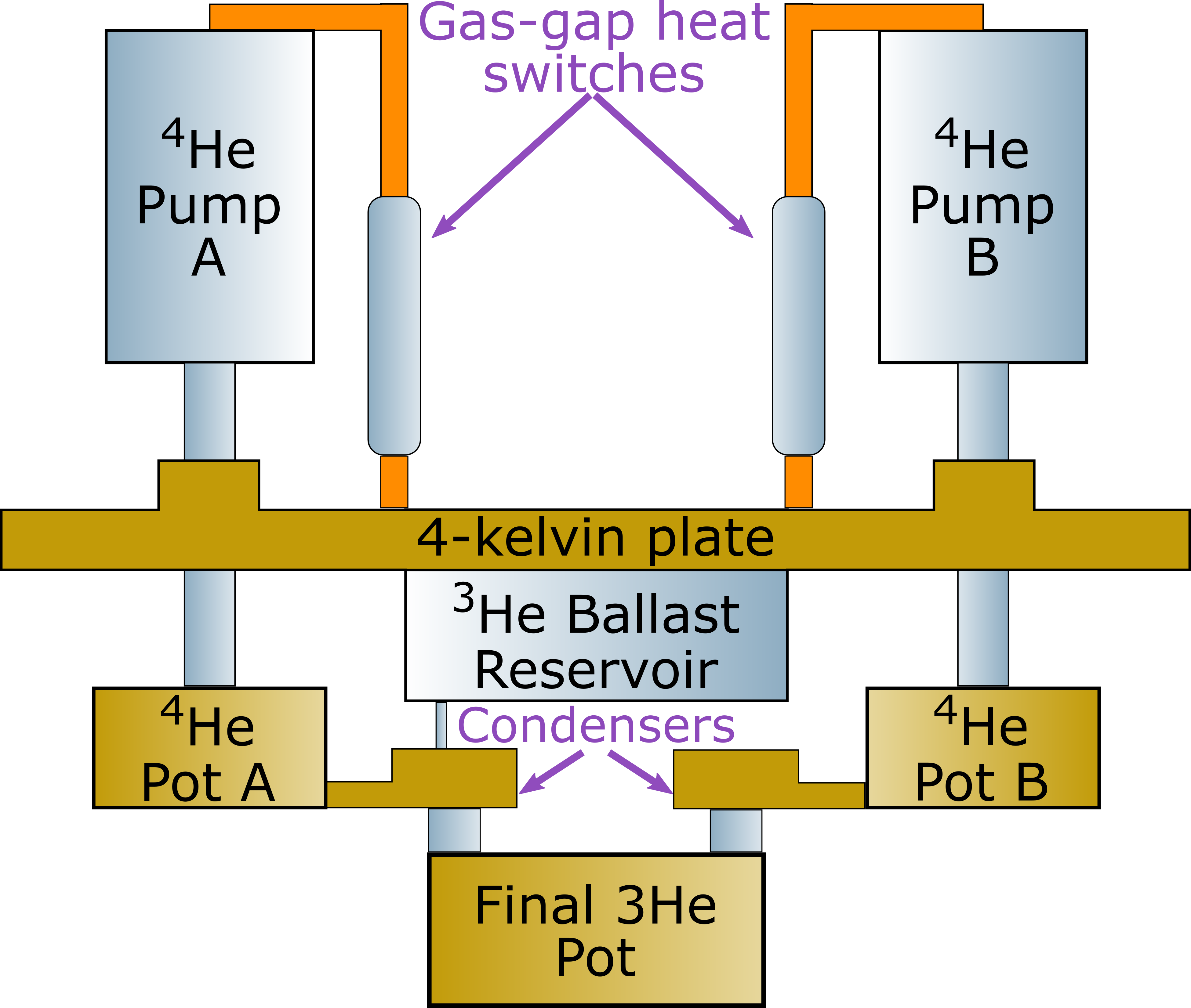
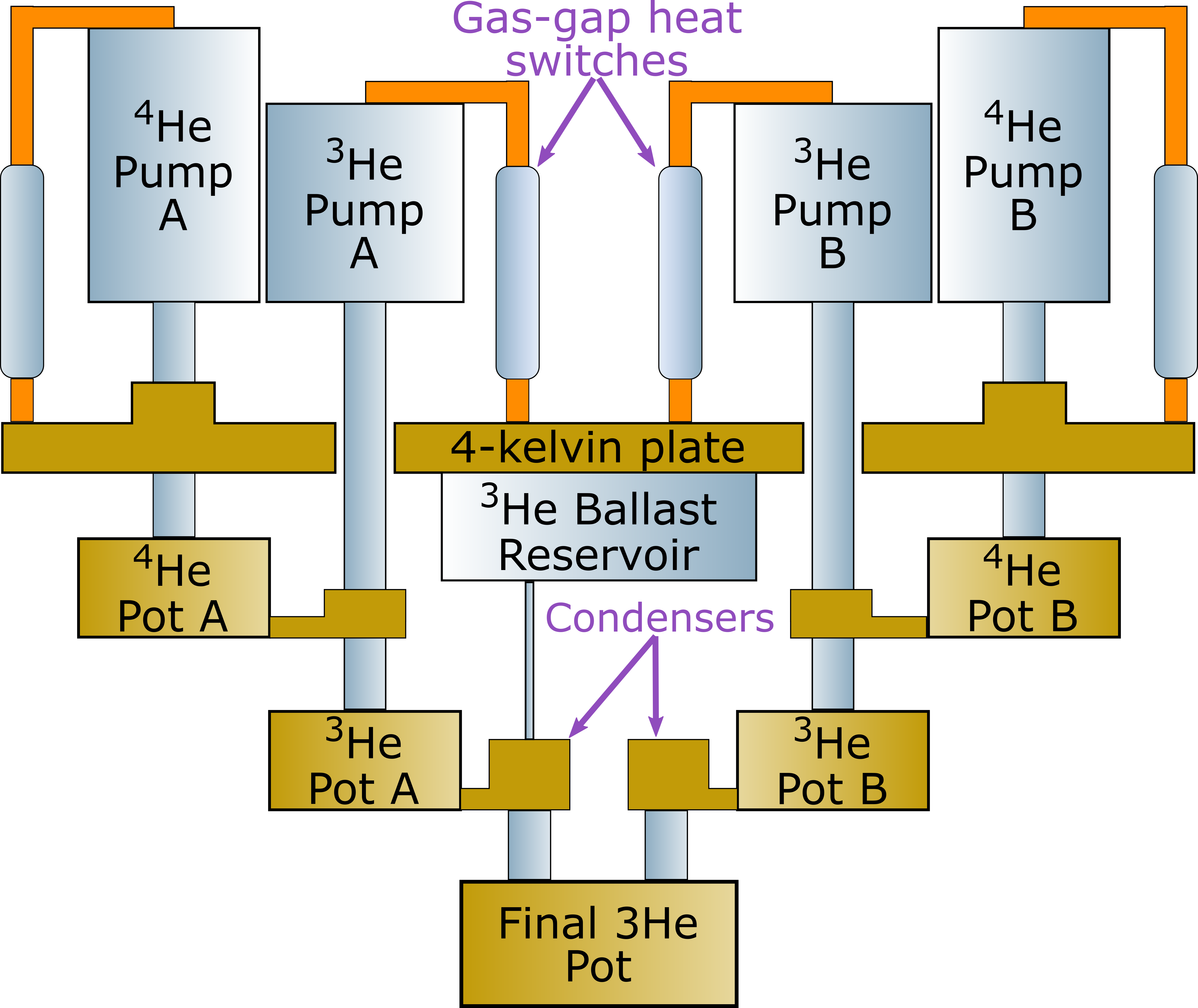
Of the three sub-Kelvin stages in MUSCAT two—the 1-K and 450-mK stages—are cooled by continuous sorption coolers. In total there are six sorption pumps used to cool these stages with two He4 pumps used to cool the 1-K stage and two sets of He4-He3 paired pumps to cool the 450-mK stage. For each stage, the pumps are divided into two subsystems (refereed to as A and B). This subsystems are recycled sequentially to provide continuous cooling. The following figures present a highly-simplified schematic of the configuration of each of these coolers.
Input Parameters
The recycling of the coolers is controlled by a state machine scripted in LabView. This state machine has two sets of input parameters each contained in a human-readable .ini file.
Hardware Configuration Parameters
The first set of parameters is the physical channel IDs of the various heaters and temperature sensors. This is purely dependent on hardware configuration and present no possibility for optimisation and so is not further discussed here.
Cycle Optimisation Parameters
The second set of parameters defines values like the set temperature each pump is heated to along with the voltage used for heating and the value of the exit condition for each stage of the cycle. The complete set of parameters is listed below
| Section | Parameter | Description | Default Value | Unit | Valid Range |
|---|---|---|---|---|---|
| CC7 | He4APumpSetT | Temperature to heat He4 A pump to condense He4 | 37.0 | Kelvin | Min: 0 |
| CC7 | He4APumpVHeat | Voltage used to heat He4 A pump up to He4APumpSetT | 24.0 | Volts | Min: 0, Max: 24 |
| CC7 | He4APumpVHold | Voltage used to hold He4 A pump at approximately He4APumpSetT during condensation | 3.5 | Volts | Min: 0, Max: 24 |
| CC7 | He4AHSVOn | Voltage to turn on (close) heat switch for He4 A pump | 3.5 | Volts | Min: 0, Max: 5 |
| CC7 | He4AHSVOff | Voltage to apply while heat switch for He4 A pump is off (open) | 0 | Volts | Min: 0, Max: 5 |
| CC7 | He3APumpSetT | Temperature to heat He3 A pump to condense He3 | 35.0 | Kelvin | Min: 0 |
| CC7 | He3APumpVHeat | Voltage used to heat He3 A pump up to He3APumpSetT | 24.0 | Volts | Min: 0, Max: 24 |
| CC7 | He3APumpVHold | Voltage used to hold He3 A pump at approximately He3APumpSetT during condensation | 3.5 | Volts | Min: 0, Max: 24 |
| CC7 | He3AHSVOn | Voltage to turn on (close) heat switch for He3 A pump | 3.5 | Volts | Min: 0, Max: 5 |
| CC7 | He3AHSVOff | Voltage to apply while heat switch for He3 A pump is off (open) | 0 | Volts | Min: 0, Max: 5 |
| CC7 | He3ASoftStartV | Voltage used to preheat He3 A pump during heating of He4 A pump | 0 | Volts | Min: 0, Max: 24 |
| CC7 | He4BPumpSetT | Temperature to heat He4 B pump to condense He4 | 37.0 | Kelvin | Min: 0 |
| CC7 | He4BPumpVHeat | Voltage used to heat He4 B pump up to He4APumpSetT | 24.0 | Volts | Min: 0, Max: 24 |
| CC7 | He4BPumpVHold | Voltage used to hold He4 B pump at approximately He4APumpSetT during condensation | 3.5 | Volts | Min: 0, Max: 24 |
| CC7 | He4BHSVOn | Voltage to turn on (close) heat switch for He4 B pump | 3.5 | Volts | Min: 0, Max: 5 |
| CC7 | He4BHSVOff | Voltage to apply while heat switch for He4 B pump is off (open) | 0 | Volts | Min: 0, Max: 5 |
| CC7 | He3BPumpSetT | Temperature to heat He3 B pump to condense He3 | 35.0 | Kelvin | Min: 0 |
| CC7 | He3BPumpVHeat | Voltage used to heat He3 B pump up to He3APumpSetT | 24.0 | Volts | Min: 0, Max: 24 |
| CC7 | He3BPumpVHold | Voltage used to hold He3 B pump at approximately He3APumpSetT during condensation | 5.0 | Volts | Min: 0, Max: 24 |
| CC7 | He3BHSVOn | Voltage to turn on (close) heat switch for He3 B pump | 3.5 | Volts | Min: 0, Max: 5 |
| CC7 | He3BHSVOff | Voltage to apply while heat switch for He3 B pump is off (open) | 0 | Volts | Min: 0, Max: 5 |
| CC7 | He3BSoftStartV | Voltage used to preheat He3 B pump during heating of He4 B pump | 0 | Volts | Min: 0, Max: 24 |
| CC7 | He4CondTemp | Temperature below which we consider He4 to condense in the system | 4.2 | Kelvin | Min: 0 |
| CC7 | He4CondTime | Time to wait for He4 to condense | 480 | Seconds | Min: 0 |
| CC7 | He3CondTemp | Temperature below which we consider He3 to condense in the system | 3.1 | Kelvin | Min: 0 |
| CC7 | He3CondTime | Time to wait for He3 to condense | 480 | Seconds | Min: 0 |
| CC7 | HSOffBelow | Temperature below which a heat switch is considered to be off (open) | 15.0 | Kelvin | Min: 0 |
| CC7 | TimeBetweenCycles | Time between the end of a A/B subsystem cycle and the start of the B/A cycle | 480 | Seconds | Min: 0 |
| CC7 | He3TimeOut | Fall-back parameter - Maximum time to wait after pumping He4 for the head of a He3 pump to cool below He3CondTemp before manually advancing the cycle | 2700 | Seconds | Min: 0 |
| CC4 | He4APumpSetT | Temperature to heat He4 A pump to condense He4 | 47.0 | Kelvin | Min: 0 |
| CC4 | He4APumpVHeat | Voltage used to heat He4 A pump up to He4APumpSetT | 24.0 | Volts | Min: 0, Max: 24 |
| CC4 | He4APumpVHold | Voltage used to hold He4 A pump at approximately He4APumpSetT during condensation | 4.5 | Volts | Min: 0, Max: 24 |
| CC4 | He4AHSVOn | Voltage to turn on (close) heat switch for He4 A pump | 5.0 | Volts | Min: 0, Max: 5 |
| CC4 | He4AHSVOff | Voltage to apply while heat switch for He4 A pump is off (open) | 0 | Volts | Min: 0, Max: 5 |
| CC4 | He4BPumpSetT | Temperature to heat He4 A pump to condense He4 | 47.0 | Kelvin | Min: 0 |
| CC4 | He4BPumpVHeat | Voltage used to heat He4 A pump up to He4BPumpSetT | 24.0 | Volts | Min: 0, Max: 24 |
| CC4 | He4BPumpVHold | Voltage used to hold He4 A pump at approximately He4BPumpSetT during condensation | 5.0 | Volts | Min: 0, Max: 24 |
| CC4 | He4BHSVOn | Voltage to turn on (close) heat switch for He4 A pump | 5.0 | Volts | Min: 0, Max: 5 |
| CC4 | He4BHSVOff | Voltage to apply while heat switch for He4 A pump is off (open) | 0 | Volts | Min: 0, Max: 5 |
| CC4 | HSOffBelow | Temperature below which a heat switch is considered to be off (open) | 15.0 | Kelvin | Min: 0 |
| CC4 | TimeAfterCC7BeforeCC4 | Time to wait after finishing the CC7 subsystem cycle before finishing the CC4 subsystem cycle | 0 | Seconds | Min: 0 |
| MD | StillVOn | Voltage applied to still heater to circulate He3 | 1.8 | Volts | Min: 0, Max: 2 |
| MD | StartStillBelowT | Temperature of still condensor (450-mK stage) below which to start circulating He3 | 0.6 | Kelvin | Min: 0 |
Example Files
Example configuration files, based on the currently used parameters are available for download here.
Cycle State Flow
The following presents a basic overview of the states used in the state-machine to recycle the coolers in MUSCAT cryostat.
The following steps assume that the pulse tube is running and system has cooled to 4 K. These preliminary steps are controlled and reported by the MUSCAT Cryogenics Control and Logging Software but are note detailed here.
- Start with all HSs
CC*He**HSVOn - Set CC4 A HS heater
CC4He4AHSVOff, go to 2 - Set CC7 A He3 and He4 HS heaters to
CC7He3AHSVOffandCC7He4AHSVOff, go to 3 - if CC4 He4A HS is <
CC4HSOffBelowgo to 4; else go to 3 - Apply
CC4He4APumpVHeatto CC4 He4 A pump heater, go to 5 - if CC7 He4 A HS AND CC7 He3 A HS <
CC7HSOffBelowgo to 6, else go to 5 - Apply
CC7He4APumpVHeatto CC7 He4 A pump heater, applyCC7He3ASoftStartVto CC7 He3 A pump heater, go to 7 - if CC7 He4 A pump >
CC7He4APumpSetTgo to 8 (once only); if CC4 He4 A pump >CC4He4APumpSetTgo to 9 (once only); if CC7 He4 A pump >CC7He4APumpSetTAND CC4 He4 A pump >CC4He4APumpSetTgo to 10; else go to 7 - Apply
CC7He4APumpVHoldto CC7 He4 A pump heater, go to 7 - Apply
CC4He4APumpVHoldto CC4 He4 A pump heater, go to 7 - Apply
CC7He3APumpVHeatto CC7 He3 A pump heater, go to 11 - if CC7 He3 A pump >
CC7He3APumpSetTgo to 12; else go to 11 - Apply
CC7He3APumpVHold, go to 13 - if CC7 He4 A head <
CC7He4CondTempgo to 14; else go to 13 - wait
CC7He4CondTimethen go to 15. - Set CC7 He4 A pump heater to 0, apply
CC7He4AHSVOnto CC7 He4A HS heater, go to 16 - if CC7 He3 A head <
CC7He3CondTempgo to 17; else if time at this state >CC7He3TimeOutgo to 17; else go to 16 - wait
CC7He3CondTime, then go to 18 - Set CC7 He3 A pump heater to 0, apply
CC7He3AHSVOnto CC7 He3A HS heater, go to 19 - wait
CC4TimeAfterCC7BeforeCC4, then go to 20 - Set CC4 He4 A pump heater to 0, apply
CC4He4AHSVOnto CC4 He4A HS heater, go to 21 - wait
CC7TimeBetweenCycles, then go to 22 - Set CC4 B HS heater to
CC4He4BHSVOff, go to 23 - Set CC7 B He3 and He4 HS heaters to
CC7He3BHSVOffandCC7He4BHSVOff, go to 24 - if CC4 He4 B HS <
CC4HSOffBelow, go to 25; else go to 24 - Apply
CC4He4BPumpVHeatto CC4 He4 B pump heater, go to 26 - if CC7 He4 B HS AND CC7 He3 B HS <
CC7HSOffBelowgo to 27, else go to 26 - Apply
CC7He4BPumpVHeatto CC7 He4 B pump heater, applyCC7He3BSoftStartVto CC7 He3 A pump heater, go to 28 - if CC7 He4 B pump >
CC7He4BPumpSetTgo to 29 (once only); if CC4 He4 B pump >CC4He4BPumpSetTgo to 30 (once only), if CC4 He4 B pump >CC4He4BPumpSetTAND CC7 He4 B pump >CC7He4BPumpSetTgo to 31, else go to 28 - Apply
CC7He4BPumpVHoldto CC7 He4 B pump heater, go to 28 - Apply
CC4He4BPumpVHoldto CC4 He4 B pump heater, go to 28 - Apply
CC7He3BPumpVHeatto CC7 He3 B pump heater, go to 32 - if CC7 He3 B pump >
CC7He3BPumpSetTgo to 33, else go to 32 - Apply
CC7He3BPumpVHoldto CC7 He3 B pump heater, go to 34 - if CC7 He4 B pump head <
CC7He4CondTempgo to 35, else go to 34 - wait
CC7He4CondTime, then go to 36. - Set CC7 He4 B pump heater to 0, apply
CC7He4BHSVOnto CC7 He4 B HS, go to 37 - if CC7 He3 B head <
CC7He3CondTempgo to 38; else if time at this state >CC7He3TimeOutgo to 38; else go to 37 - wait
CC7He3CondTime, then go to 39 - Set CC7 He3 B pump heater to 0, apply
CC7He3BHSVOnto CC7 He3B HS heater, go to 40 - wait
CC4TimeAfterCC7BeforeCC4, then go to 41 - Set CC4 He4 B pump heater to 0, apply
CC4CC7He4BHSVOnto CC4 He4B HS heater, go to 42 - wait
CC7TimeBetweenCycles, then go to 1
Miniature Dilution Refrigerator
The cycle described above does not consider the operation of the miniature dilution refrigerator used to cool the detectors from 450 mK to 120 mK. A dilution refrigerator )either standard or miniature) is inherently continuous and thus does not require recycling in the same way that a sorption-cooler based system does. The miniature dilution refrigerator simply requires a static thermal power to be applied to its still (also known as the evaporator). In theory this power could be applied at all times including during the cooldown from 300 K, however the reality of doing this would be that cooldown of the 450-mK stage from 4 K to its base temperature would take longer were this done. Instead the state machine used to cycle the continuous sorption coolers monitors the cooldown of the 450-mK stage and when appropriate applies the thermal load to the still. To do this the state machine is modified as follows:
- A flag variable called
FocalPlaneReadyis added with a default value ofFalse - If at Step 39 above the temperature of the miniature dilution refrigerator's mixing chamber (the detector stage of MUSCAT) is above
MDStartStillBelowT,FocalPlaneReadyis set toFalse, the still heater is switched off (0 V applied) and the state machine advances to Step 40 - If at Step 39 above the temperature of the miniature dilution refrigerator's mixing chamber is below
MDStartStillBelowTANDFocalPlaneReadyisFalse,FocalPlaneReadyis set toTrue, the still heater is left off (with 0 V applied) and the state machine moves on to Step 40 - If at Step 39 above the temperature of the miniature dilution refrigerator's mixing chamber is below
MDStartStillBelowTANDFocalPlaneReadyisTrue(that is to say the above condition was met on the previous B sub-system cycle), the still heater is set toMDStillVOnand the state machine moves on to Step 40