Closing the MUSCAT Cryostat
Installing the 450-mK Shield
info
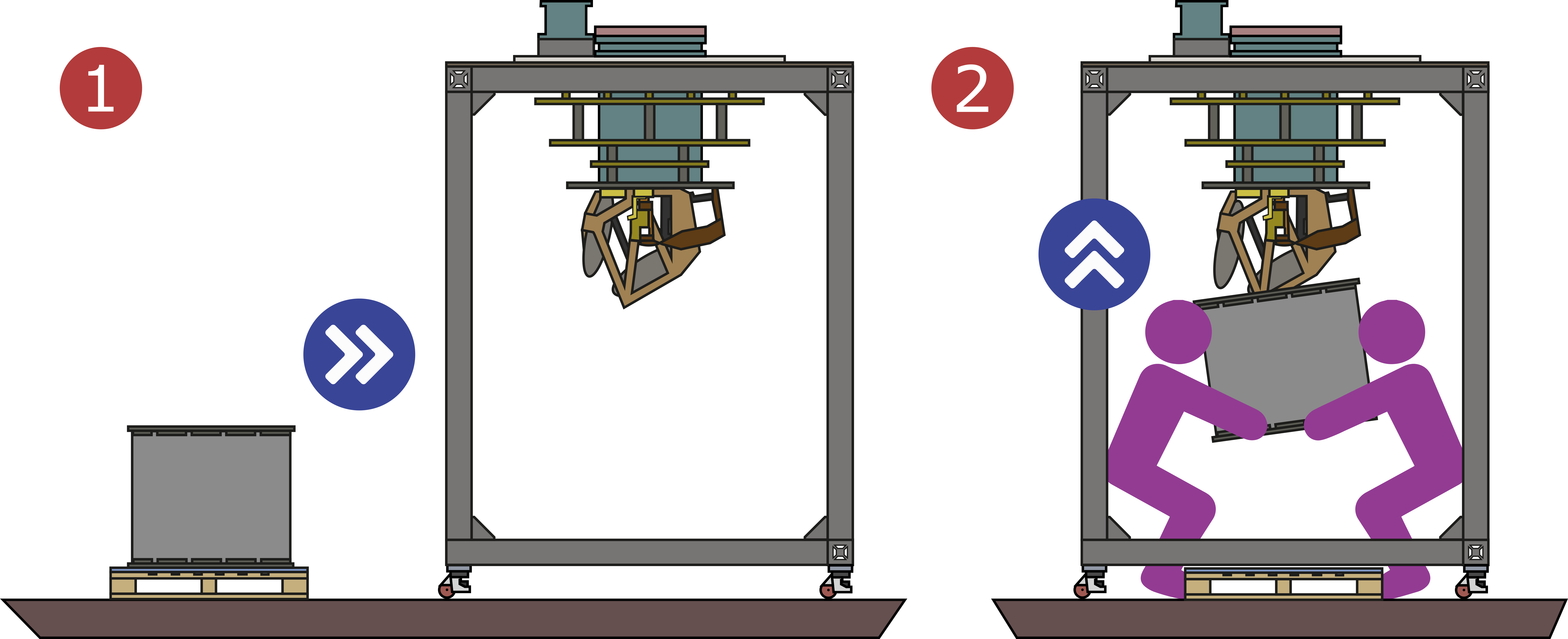
This step requires at least three people. Two to lift and locate the shield and one to secure the initial bolts.
- With the 450-mK shield below MUSCAT approximately orientate the shield so the coloured alignment marks on the top rim of the shield and the edge of the 450-mK plate. Using two people.
- Using two people, lift the shield into place. It will need to be tilted to clear the internal components at the 450-mK stage. Extreme care should be taken not to damage the tubes of the miniature dilution refrigerator, these contain the He4/He3 mix and are at high pressure (70 Bar, 1000 PSI).
- Place the bolts (with washers) to secure the 450-mK shield to the plate. These bolts are places through the 450-mK plate and screw into the 450-mK shield.
- Plug in the 450-mK lid RTD at the interface between the shield and the plate, there is an orientation marker on each part of the connector.

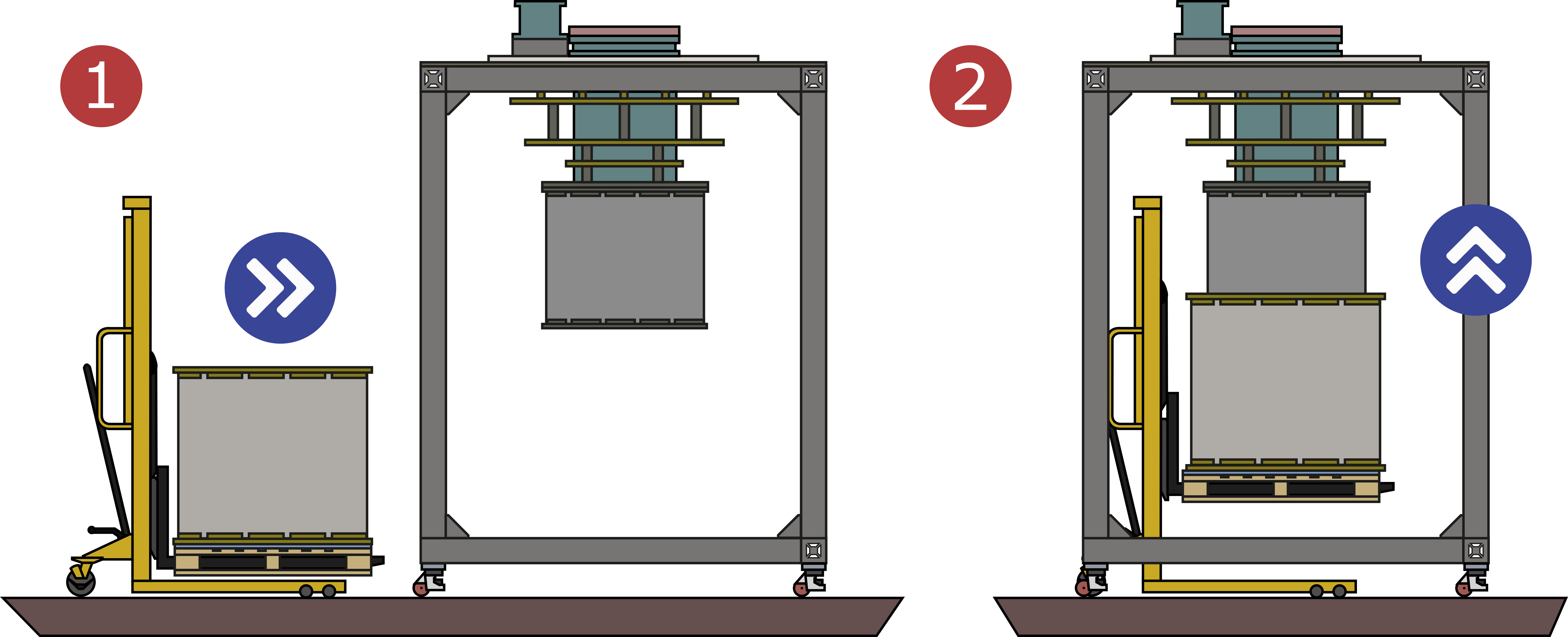
Installing the 4-Kelvin Shield
- Place the 4-Kelvin shield on appropriate lifting equipment orientated such that the alignment marks align on the plate edge and the top rim of the shield.
- Using the lifting equipment, raise the 4-Kelvin shield around the 450-mK shield taking care not to catch or damage the 450-mK shield.
- At the two positions marked with an asterisk (
*), place bolts through the 4-Kelvin plate and tighten them into the pre-installed nuts in the 4-Kelvin can. - In the remaining bolt holes, locate the bolts through the 4-Kelvin shield and screw them into the tapped holes in the plate.
- Plug in the 4-Kelvin lid diode sensor at the interface between the shield and the lid, there is an orientation marking in each part of the connector.

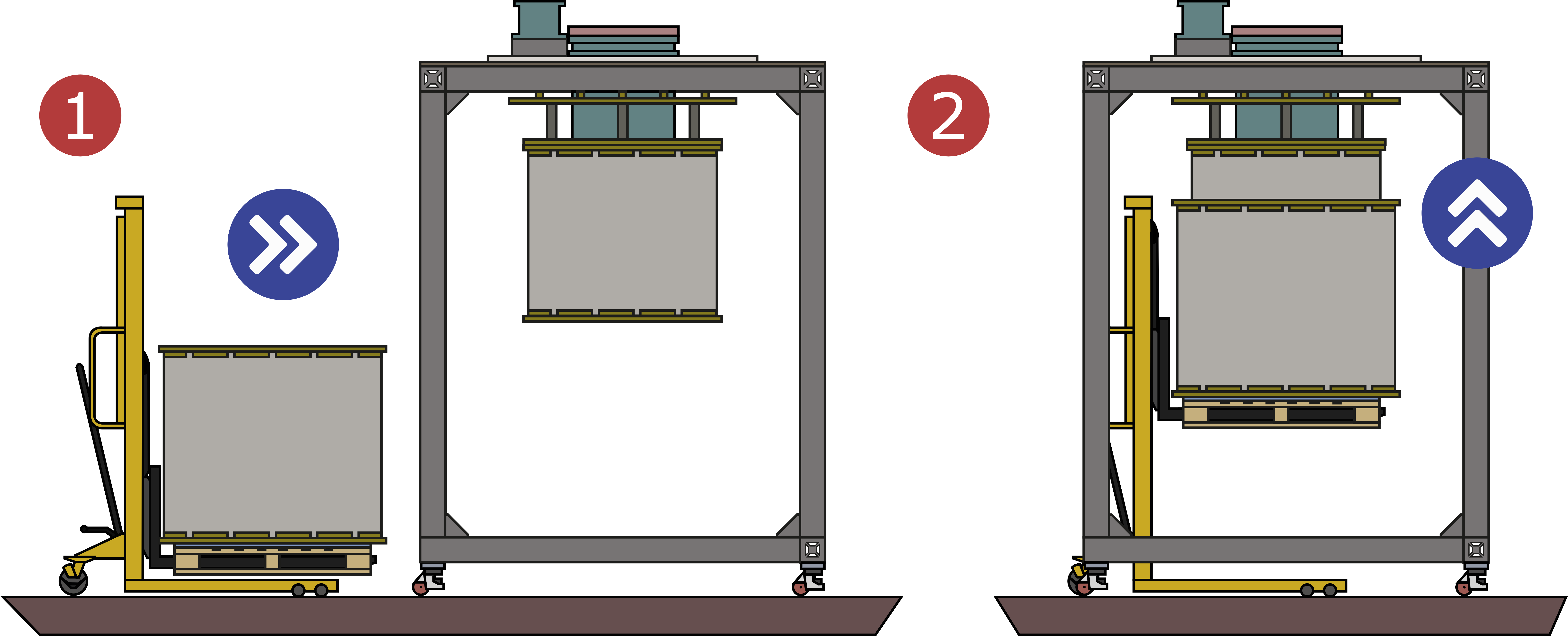
Installing the 50-Kelvin Shield
- Place the 50-Kelvin shield on appropriate lifting equipment orientated so the alignment marks align on the plate edge and the top rim of the shield.
- Using the lifting equipment, raise the 50-Kelvin shield around the 4-Kelvin shield taking care not to catch or damage the 4-Kelvin shield.
- Secure the 50-Kelvin shield by installing the bolts and washers around the perimeter of the shield. The bolts should pass through the 50-Kelvin shield and be screwed into the preinstalled nuts in the shield.
- Plug in the 50-Kelvin lid diode sensor at the interface between the shield and the lid, there is an orientation marking in each part of the connector.

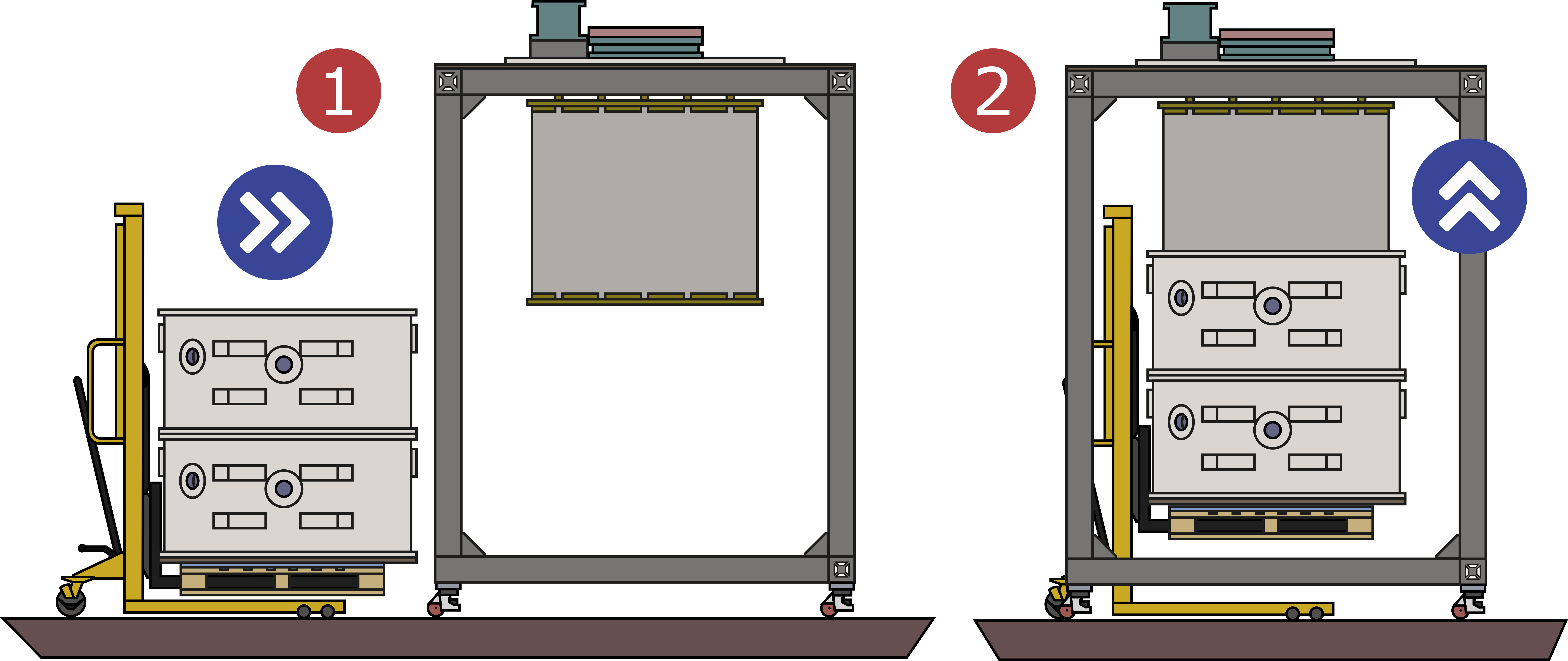
Installing the Vacuum Can & Drawing Vacuum
- With the vacuum can positioned under the cryostat (mounted on the work frame) and mounted on lifting equipment, orientate the can so the bolts coming through the top plate align with the clearance holes in the vacuum can.
- Inspect the rubber o-ring and groove in the vacuum can for any dirt and clean as required. Inspect the mating surface on the underside of the cryostat top plate and clean as needed.
- Raise the vacuum can into place so the bolts from the top plate pass through the holes in the vacuum can but not do not bring the can or the rubber o-ring into contact with the top plate. Take care not to catch or damage the 50-Kelvin shield while raising the vacuum can. A small shake of the vacuum can is normally needed to help the bolts drop through the holes.
- Loosely install the washers and nuts on the bolts.
- Slowly raise the vacuum can by tightening each nut a little at a time. Ensure the vacuum can is raised as level as possible. Continue until the gap between the vacuum can and the top plate has been reduced to approximately 3 mm.
- Connect a turbo vacuum pump at the vacuum port of the cryostat and ensure the vacuum valve is opened fully.
- Start the turbo pump.
- If after a few minutes (depends on the capacity of the pump used) there is no signs of a vacuum being drawn (either a decrease in pressure on a vacuum gauge or the nuts on the vacuum bolts between the top plate and the vacuum can becoming loose), tighten each nut a little and wait to see if a vacuum develops. Repeat this until the pressure is decreasing.
tip
It is important to use the vacuum pump to bring the can into contact with the top plate. Due to the imperfections in the work frame and lifting equipment, and the large diameter of the MUSCAT cryostat, simple tightening the bolts will likely mean the vacuum can is not perfectly levelled to the top plate and is then jammed in place by the bolts. This will result in vacuum leaks.

Removing the Cryostat from the Work Frame
- Place appropriate lifting equipment under bottom of the vacuum can to support the cryostat. The lifting equipment should be in contact with the underside of the vacuum can and locked to ensure it doesn't drop away.
- Remove and store the bolts from the outer perimeter of the top plate which secure the cryostat to the clam plate of the work frame.
- Remove and store the bolts and washers from the long edge of each clam plate. Loosen (but do not remove) the bolts in the slots on the short edge of each clam plate.
- Using the lifting equipment, raise the cryostat a small amount so it just lift up from the clam plates of the work frame.
- Moving each plate in turn a little at a time, slide the clam plates upon. Make sure the plates are slid open evenly to the work frame doesn't become unstable and tip.
- Using the lifting equipment, lower the cryostat through the opened clam plates.
- Close the clam plates by moving each plate a little at a time and alternating between the two plates. Make sure the frame does not become unbalanced and tip. Tighten the bolts in the slots located on the short edges of the clam plates and reinstall the bolts and washers on the long edges and tighten these.
